Pixeldoc2000 (talk | contribs) (added some stuff like bus pirate, SD900 and more) |
Pixeldoc2000 (talk | contribs) m (corrected Image description) |
||
| Line 50: | Line 50: | ||
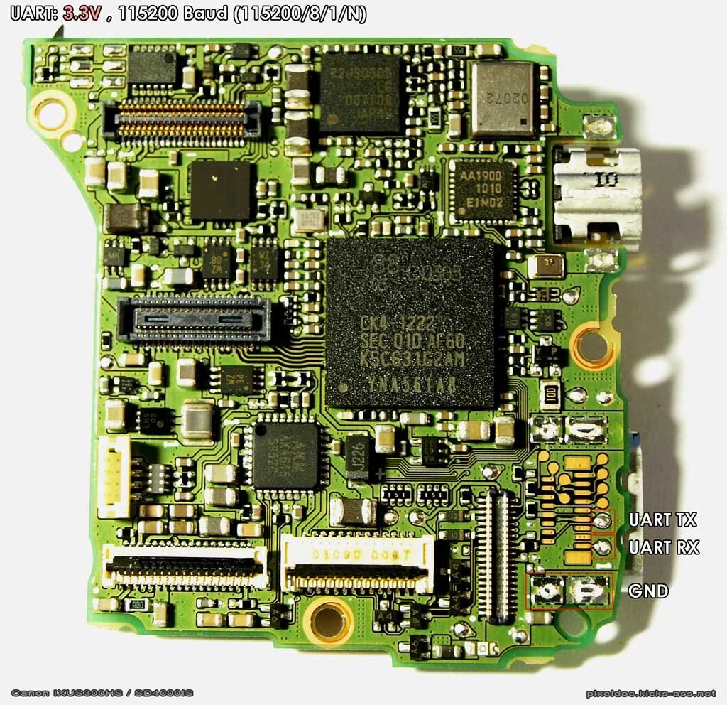
=== [[SD4000]] === |
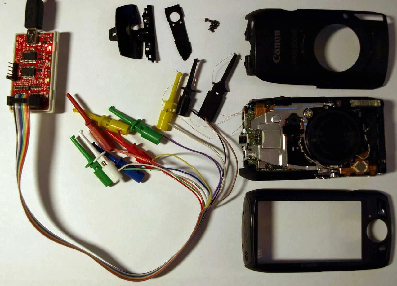
=== [[SD4000]] === |
||
| − | [[File:Canon_ixus300_sd4000_uart.jpg|512px|Canon |
+ | [[File:Canon_ixus300_sd4000_uart.jpg|512px|Canon SD4000 UART Pinout]] |
| − | [[File:Canon_ixus300_sd4000_uart_buspirate.jpg|512px|Canon |
+ | [[File:Canon_ixus300_sd4000_uart_buspirate.jpg|512px|Canon SD4000 UART connected to Bus Pirate]] |
===[[SD900]]=== |
===[[SD900]]=== |
||
Revision as of 16:24, 28 June 2011
after reading User:Pixeldoc2000's description of the UART port on the SD4000, i investigated this a little and located the UART connections for all cameras i had on hand...
about the UART port in general
it appears that every canon camera has a serial port that gives access to a shell (command line interface) that lets you control the camera even without chdk loaded. it might also be useful to recover possibly bricked cameras by giving access to a bootloader.
on all cameras you get access to the Event Shell, DryOS cameras also have a DryOS Shell.
note that this is not _that_ interesting, as with CHDK's PTP Extension you can accesss the camera more conveniently via USB, without requuiring hardware modificationss.
locating the uart connection points
this is relatively simple if you have access to an oscilloscope or logic analyzer. it took me only a few minutes on most cameras.
the camera will always send a short string (just the event-shell prompt) when booting. so just probe on the pcb while power-cycling the camera until you find that transmission, then you have the TxD pin... RxD is usually right next to it. (but testing RxD takes a little more care, as you have to connect an external signal here, and might break something when connecting too the wrong pin.)
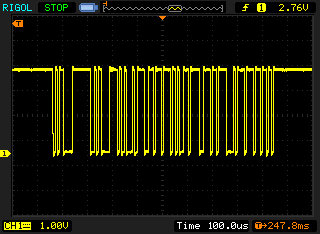
Canon SD4000 UART RX Scope Screenshot
(todo: note idle voltages of both pins).
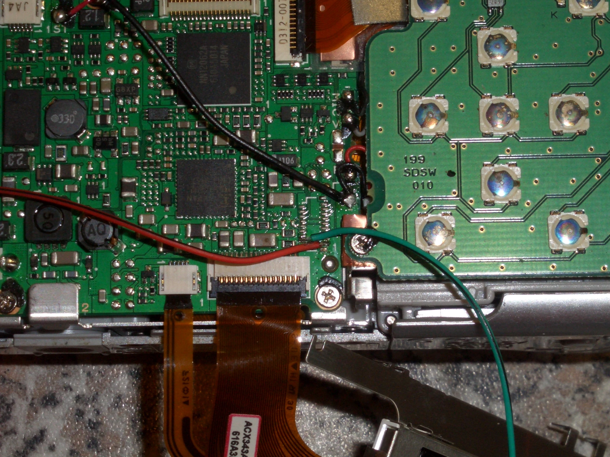
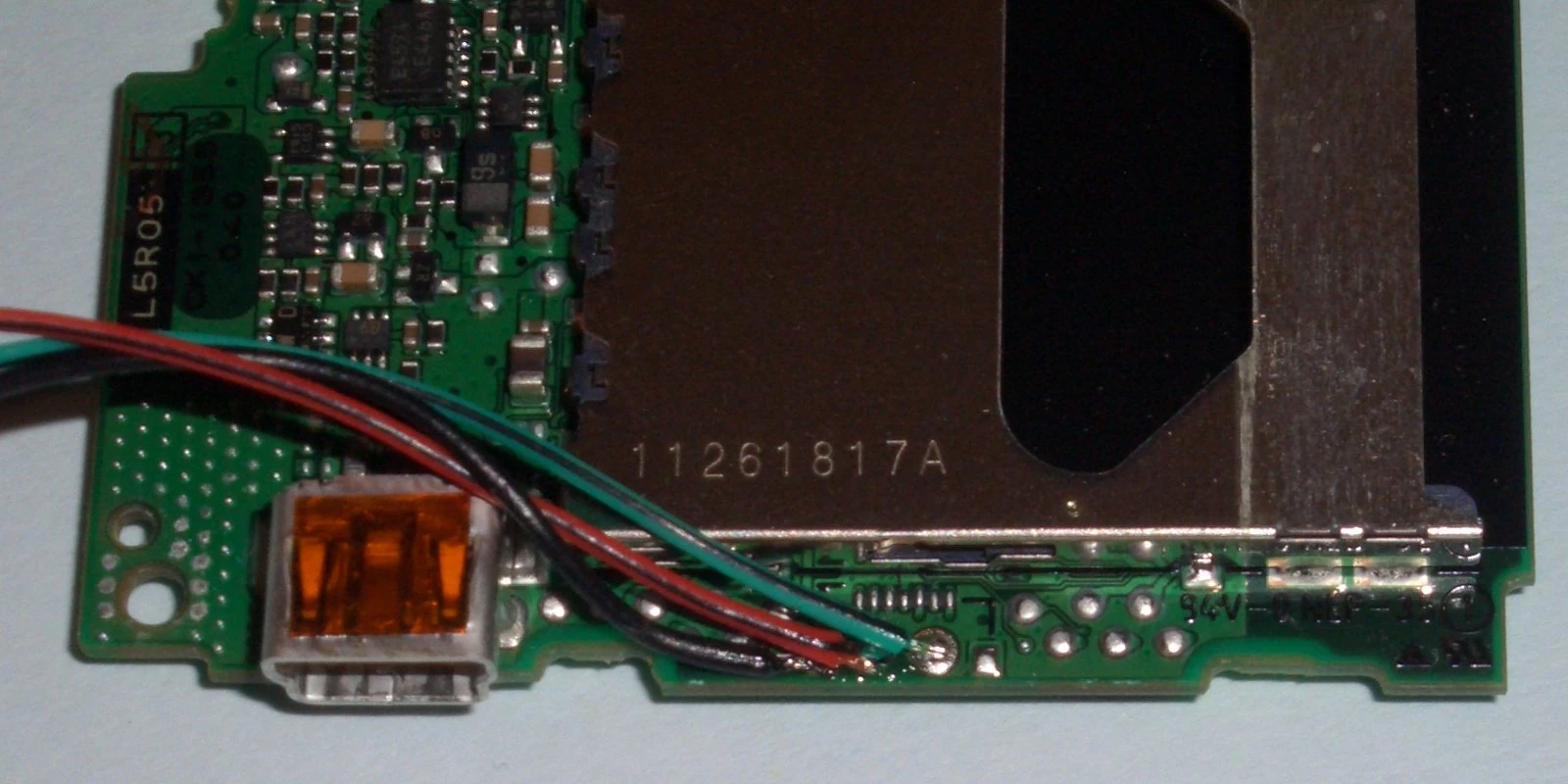
almost all camera have an (usually unpopulated) debug/factory test connector on the pcb, usually close to the USB port. and usually the first pin on that connector is RxD and the second is TxD. also both signals are in most cases available on test-points right next to the connetor (more convenient to solder). (GND can be grabbbed at the connector shield/mount, or any convenient point.)
see the pictures below for some examples.
settings/usage
to connect to the port you will need a serial interface with 3.3V TTL levels.
UART Settings: 115200/8/1/N (115200 Baud)
Voltage Level: 3.3V (TTL)
USB to Serial Interfaces can for example be bought on ebay (search for "ttl rs232" and include international sellers, they are just a few bucks, with shiping from china).
FTDI sells USB TTL Serial Cables like TTL-232R-3V3 which are perfect for the job.
Bus Pirate is also a very nice hacking tool (supports UART 3.3V & 5.0V, JTAG, I2C, SPI and more).
uart connections for some cameras
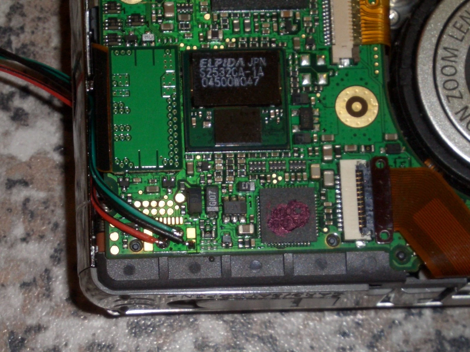
in all my pictures:
red=TxD (this is an output, be careful not to short it, that might break the camera)
green=RxD
BLACK=GND
SD4000
SD900
SD900 also have UART. ToDo: add PCB Picture and Pinout.
IXUS40
Powershot_A530
IXUS 750
PowerShot S2IS
i had no luck here, the debug connector is actually soldered in, but you need to almost completely disassemble the camera to get to it, it's a ZIF connector for a ribbon cable of very fine pitch that i did not have around. also be careful, this camera appears very sensitive due to high integration and the many PCBs... i actually broke one camera when taking it apart. :(